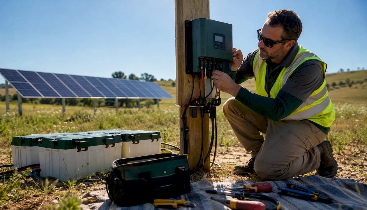
An MPPT (Maximum Power Point Tracker) controller acts as a DC-to-DC converter that continuously finds the voltage and current combination where your solar panels produce the most power, then converts that to the exact voltage your battery needs. The result: more usable energy from the same panels, every hour of every day.
Use MPPT when:
- Your array exceeds ~200W, uses series-wired panels, operates in cold climates, or feeds LiFePO4 batteries
- You plan to expand your system or run long cable runs from panels to batteries
PWM may be acceptable when:
- You have a small, warm-weather 12V system under ~200W with closely matched panel and battery voltages and no plans to expand
Modern MPPT controllers typically achieve high conversion efficiency, and algorithms like Perturb & Observe (P&O) and Incremental Conductance are the industry standard for tracking that moving power point. U.S. installations must also meet NEC and UL/ETL requirements, which we cover in the safety section below.
Table of Contents
- How does MPPT solar charging actually work?
- When does MPPT outperform PWM, and by how much?
- How does MPPT interact with LiFePO4 and other battery chemistries?
- How do you size an MPPT controller correctly?
- What does a safe U.S. MPPT installation look like?
- How do you troubleshoot common MPPT problems?
- When is MPPT not worth the extra cost?
- Key Takeaways
- Why Toddra recommends MPPT for portable and backup systems
- Toddra portable power stations work with your MPPT setup
- Useful sources and further reading
How does MPPT solar charging actually work?
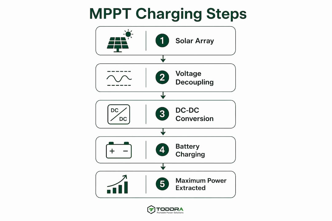
An MPPT controller decouples array and battery voltages, which is the key physical difference from a PWM controller. A PWM controller connects the panel almost directly to the battery, forcing the panel to operate at battery voltage. An MPPT controller inserts a DC-to-DC conversion stage between them, so the panel runs at its own optimal voltage (Vmp) while the battery receives whatever voltage it needs.
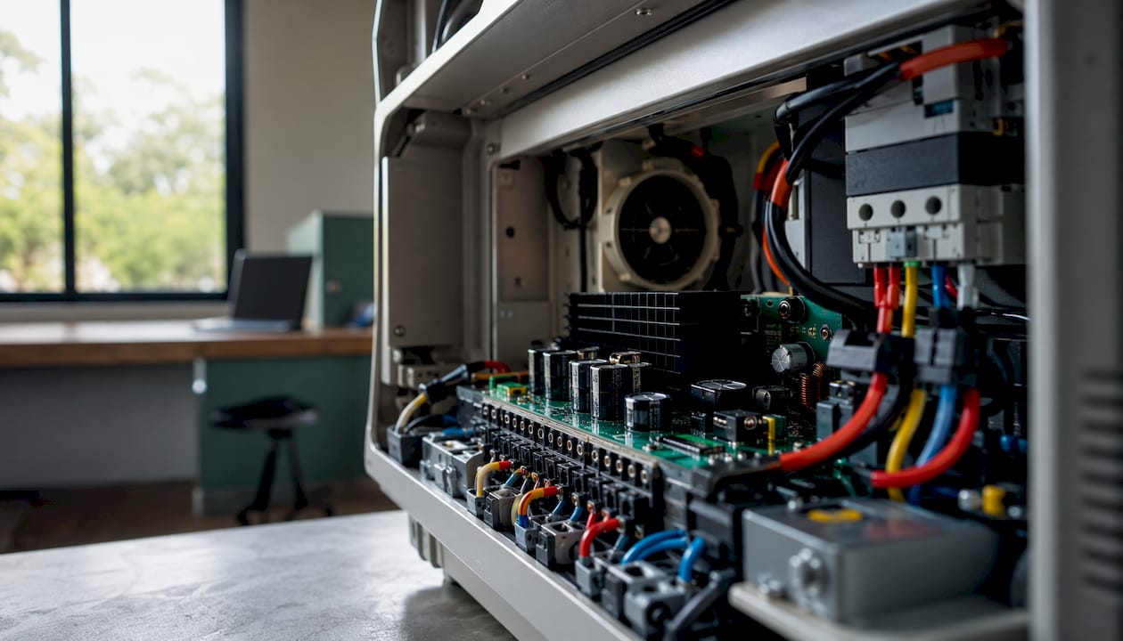
The conversion path looks like this: solar array → MPPT DC-to-DC converter → battery bank. Inside the converter, DC input is switched to high-frequency AC (typically 20–80 kHz), passed through a high-efficiency transformer, and rectified back to DC at the target charging voltage. The output current is higher than the input current whenever input voltage exceeds output voltage, following the relationship Iout ≈ (Vin/Vout) × Iin × η, where η is conversion efficiency.
MPPT algorithms continuously adjust the operating point to stay at peak power. The three most common approaches are:
| Algorithm | How it works | Best for |
|---|---|---|
| Perturb & Observe (P&O) | Nudges voltage up or down, measures power change, repeats | General use; simple and reliable |
| Incremental Conductance | Compares dI/dV to I/V to find MPP mathematically | Faster response to rapid irradiance changes |
| Fuzzy Logic | Uses rule-based inference to predict MPP shifts | Partial shading and complex multi-peak curves |
Key insight: On a partly cloudy day, the panel's I-V curve can shift its peak power point dozens of times per minute. A controller running P&O or Incremental Conductance tracks that moving target continuously, while a PWM controller simply cannot — it has no conversion stage to exploit the gap between panel voltage and battery voltage.
When does MPPT outperform PWM, and by how much?
MPPT increases energy capture by roughly 25–40% compared to a direct panel-to-battery connection, though the real-world range depends heavily on conditions. In hot weather with well-matched 12V panels, the advantage can shrink to 5–10%. On cold, sunny mornings or during partial shading, MPPT recovers the full 25–40% margin.
MPPT is clearly the right choice when:
- Panels are wired in series (array voltage exceeds battery voltage significantly)
- The system operates in cold climates, where panel Vmp rises well above battery voltage
- Cable runs are long (higher array voltage reduces current and wire losses)
- You expect to add panels later
PWM can work when:
- The system is a small, warm-weather 12V kit under ~200W
- Panel Vmp closely matches battery charging voltage
- Budget is the primary constraint and no expansion is planned
| Scenario | Recommended controller | Reason |
|---|---|---|
| Small 12V kit, <200W, warm climate | PWM acceptable | Voltage gap is small; efficiency difference is minor |
| Series string, 2+ panels | MPPT required | Array voltage far exceeds battery voltage |
| Cold climate (any size) | MPPT required | Cold panels produce higher Vmp; PWM wastes the surplus |
| Long cable run (>30 ft) | MPPT preferred | Higher array voltage reduces current and cable losses |
| LiFePO4 battery bank | MPPT strongly preferred | CC/CV profile and fast charging demand precise current control |
For systems above ~200W, the payback period is typically 1–2 years under typical U.S. insolation. Most professionals recommend MPPT even for borderline systems because the cost difference is modest and the flexibility gained is permanent.
How does MPPT interact with LiFePO4 and other battery chemistries?
MPPT changes how much current is available, but it must coordinate with the battery's CC/CV charging profile and the battery management system (BMS). This coordination is where MPPT's advantages become most tangible for LiFePO4 users.
During the bulk (CC) phase, the MPPT supplies maximum available current up to the controller's rated output. Because MPPT harvests more power from the array than PWM can, bulk charging finishes faster. When the battery reaches its absorption voltage setpoint, the controller transitions to CV mode, holding voltage steady while current tapers. LiFePO4 batteries benefit directly from this behavior: faster bulk recovery extends cycle life by reducing the time spent at partial state-of-charge, and the precise CV transition prevents overcharge stress.
For LiFePO4 compatibility, set absorption voltage to the manufacturer's specification (typically 3.45–3.65V per cell, or 13.8–14.6V for a 12V bank). Float voltage should be set equal to or slightly below absorption for LiFePO4, since these cells do not need a sustained float the way lead-acid batteries do. When the BMS signals full charge and disconnects, a well-configured MPPT will reduce output to a safe trickle rather than spiking voltage, protecting both the controller and the battery.
How do you size an MPPT controller correctly?
Start with the basic output current formula: controller output current ≈ panel watts ÷ battery charging voltage. Always add at least 25% margin for safety and temperature variation.
Worked example 1 — 200W array into a 12V battery:
- Output current = 200W ÷ 14.4V ≈ 13.9A
- With 25% margin: 13.9 × 1.25 ≈ 17.4A → choose a 20A controller
Worked example 2 — 1,000W array into a 48V battery:
- Output current = 1,000W ÷ 57.6V ≈ 17.4A
- Input current at 100V array Vmp: 1,000W ÷ 100V = 10A (thinner wire needed on the array side)
- With margin: choose a 20A or 30A controller rated for your array's open-circuit voltage
Cable sizing and the I²R advantage:
Doubling array voltage halves current and can reduce cable cross-sectional area by up to four times for the same power level, cutting both copper cost and resistive losses (P_loss = R × I²). A 48V array string running 50 feet to the controller needs far thinner wire than a 12V string carrying the same wattage.
Cold-weather Voc correction (critical for U.S. installations):
| Step | Action |
|---|---|
| 1. Find panel Voc at STC | Check the panel datasheet |
| 2. Find temperature coefficient (Voc) | Typically about −0.3% per °C |
| 3. Find lowest expected temperature | Use local ASHRAE or NEC 690.7 data |
| 4. Calculate cold Voc | Voc_cold = Voc_STC × [1 + (coeff × ΔT)] |
| 5. Verify controller rating | Controller max Voc must exceed Voc_cold with headroom |
Never size a controller to its absolute maximum Voc. NEC 690.7 requires a 1.25× safety factor on calculated Voc for U.S. installations.
What does a safe U.S. MPPT installation look like?
The three non-negotiable checks are correct Voc headroom, proper fusing on both the PV and battery sides, and a controller with a UL or ETL listing. Everything else builds on those three.
Installation safety checklist:
- Verify controller max input Voc exceeds cold-corrected array Voc (NEC 690.7 × 1.25)
- Install a fused disconnect or breaker on the PV input, sized per NEC 690
- Install a fused disconnect on the battery output, as close to the battery as practical
- Use wire gauges rated for the calculated current with NEC ampacity derating for conduit fill and ambient temperature
- Ground the controller chassis per NEC 690.43 and manufacturer instructions
- Mount in a ventilated location; most controllers derate output above 40–45°C ambient
- Confirm UL 1741 or ETL listing for grid-tied or hybrid systems; UL 508A for standalone off-grid panels
For safe solar charging practices, always disconnect the battery before the PV array when wiring or servicing the controller.
Pro Tip: Install the controller as close to the battery as the layout allows. The high-current battery-side wiring is the most expensive run; keeping it short saves money and reduces resistive losses. Run the longer, thinner wire on the high-voltage PV side instead.
How do you troubleshoot common MPPT problems?
Most MPPT failures trace back to three causes: wiring errors, overvoltage events, and thermal shutdown. Identifying which one is happening usually takes less than five minutes.
Start by checking input polarity and measuring array Voc with a multimeter before connecting to the controller. If Voc exceeds the controller's rated maximum, even briefly, the internal converter can fail permanently. Next, inspect fuses and breakers on both the PV and battery sides. A blown fuse often means a wiring fault or a momentary overcurrent, not a failed controller.
If the controller powers on but shows low output, check for thermal derating. Most controllers display a temperature warning or reduce output above their rated ambient. Ensure vents are clear and airflow is adequate. Also verify that the BMS has not disconnected the battery, which can cause the controller to see an open circuit and shut down its output.
For ongoing reliability, check firmware update availability annually, inspect terminal connections for corrosion every six months, and log daily production data. A sudden drop in daily yield with no change in weather is the clearest early warning of a failing controller or a developing panel issue.
When is MPPT not worth the extra cost?
MPPT is usually unnecessary for very small, warm-weather 12V systems under ~200W, especially when panel Vmp closely matches battery charging voltage and no expansion is planned. In those cases, the efficiency gain may not justify the $30–$80 price premium over a comparable PWM controller.
Quick 30-second decision checklist:
- System wattage above 200W? → MPPT
- Panels wired in series or array voltage above 18V for a 12V battery? → MPPT
- Distance from panels to battery exceeds 30 feet? → MPPT preferred
- Cold climate (below 32°F regularly)? → MPPT
- LiFePO4 batteries? → MPPT strongly preferred
- None of the above? → PWM may be sufficient; re-evaluate if you expand
For portable power stations with built-in solar input ports, the MPPT circuit is usually already integrated inside the unit. Understanding solar panel campsite charging setups helps clarify when an external controller adds value versus when the station handles it internally.
Key Takeaways
MPPT is the right choice for any solar system above 200W, using series-wired panels, operating in cold climates, or charging LiFePO4 batteries, and it typically pays back its cost within 1–2 years.
| Point | Details |
|---|---|
| MPPT efficiency range | Modern controllers achieve high conversion efficiency; energy gains of 25–40% over direct connections in cold or shaded conditions. |
| PWM threshold | PWM is acceptable for warm-weather 12V systems under ~200W with closely matched panel and battery voltages. |
| Sizing formula | Output current ≈ panel watts ÷ battery charging voltage; always add 25% margin and verify cold Voc against NEC 690.7. |
| LiFePO4 compatibility | MPPT's CC/CV coordination speeds bulk charging and protects cycle life; set absorption and float voltages per manufacturer specs. |
| Toddra fit | Toddra portable power stations and expansion batteries are designed for MPPT-fed solar input; check product pages for input voltage ceilings before sizing your controller. |
Why Toddra recommends MPPT for portable and backup systems
At Toddra, we consistently recommend MPPT controllers to customers pairing solar panels with our portable power stations and expansion batteries. The reason is straightforward: our products use LiFePO4 chemistry, and MPPT's CC/CV coordination is what makes fast, safe solar recharging possible. A PWM controller simply cannot deliver the precise bulk current and clean voltage transition that LiFePO4 cells need for both speed and longevity.
When pairing an MPPT controller with a Toddra station, check the product page for the maximum solar input voltage and current ratings before sizing your array. Exceeding the input ceiling, even briefly during a cold morning, can trip the internal BMS or damage the input stage. Our support team can help you verify your panel's cold Voc, confirm controller compatibility, and walk through the configuration for your specific setup.
MPPT also improves reliability in backup scenarios by smoothing variable PV input and reducing stress on the power-conditioning chain, which matters most when you need the system to perform during an outage, not just on a sunny afternoon.
Toddra portable power stations work with your MPPT setup
Reliable solar recharging starts with hardware that was built for it. Toddra portable power stations and expansion batteries accept solar input designed for MPPT-fed charging chains, so you get fast, safe recharge without guessing at compatibility.

Key compatibility points to check on any Toddra product page:
- Maximum solar input voltage (Voc ceiling)
- Maximum solar input current
- Recommended MPPT controller output voltage range
- BMS protection behavior at full charge
For larger setups, the Jackery Battery Pack 5000 Plus expansion battery offers 5,040Wh of LiFePO4 capacity designed to integrate into expandable solar charging systems. Browse the full range of portable power stations and solar generators at Toddra, or reach out to our U.S.-based support team to get help sizing your MPPT controller and verifying Voc headroom before you buy.
Useful sources and further reading
The figures and algorithms in this article draw from the following primary technical references. Before installation, always pull your panel's datasheet to confirm Voc and the temperature coefficient used in cold-weather Voc calculations.
| Source | What it covers |
|---|---|
| Victron Energy — PWM vs MPPT technical paper | DC-to-DC conversion, series wiring, cable sizing math |
| Yokogawa — MPPT charge controllers application note | Algorithm comparisons, reliability in off-grid and hybrid systems |
| Lossless Energy — MPPT explained | Efficiency ranges, LiFePO4 CC/CV guidance, payback analysis |
| NAZ Solar Electric — MPPT charge controllers | Practical sizing, conversion efficiency, real-world gain ranges |
| Wikipedia — Maximum power point tracking | Algorithm theory, I-V curve physics, grid-tied vs off-grid behavior |
Additional reading:
- Review NEC Article 690 (Solar Photovoltaic Systems) for U.S. wiring and overcurrent protection requirements
- Check your controller manufacturer's datasheet for Voc derating tables and ambient temperature limits
- For solar panel efficiency fundamentals, this contractor-oriented primer covers the panel-side variables that affect how much power your MPPT has to work with